|
Index
Rotation
Radians, rather than degrees, are used as a measure of rotation in some image processing programs (e.g., SPM). 1 radian=the number of degrees in the angle in a circle for which the arc and radius of the angle are equal.
Planes of Section The information and images included below about planes, have been taken directly from: http://www.madsci.org/~lynn/VH/planes.html. Please visit that site to learn more and to see helpful animations.
Translation
Table Interpretation The table demonstrates how image orientation is affected by various flips and conversions. Note that such values can never be absolute, but only relative to the original image: ROWS 1) Our original images were in the orientation described on line #1 (Afni). * in this case means that the criteria for judgement are different for afni than spm. In these particular cases: Up
is Up: Slice #1 is at the bottom of the head (in axial view) and
3) MRIcro is a freeware image processing program for the PC. It does a nice job of converting the anatomical image files, but leaves them in a different orientation than the M-files. This line represents the default conversion choices for a 2D image. 4) In MRIcro, if you check "First file is dorsal" in the image conversion routine, the result resembles the SPM Template image EXCEPT that L-R flipping has not been done. 5) If you check "First file is dorsal" AND "flip L-R" in the image conversion routine, the result is equivalent to the SPM Template image. 6-12) If you have created an image file as in line #2, you can then use SPM to display it and flip it in various directions (x,y,z). These detail the results of all possible flips. Note that in our case, flipping on x,y, and z results in a file in exactly the same orientation as the SPM template. COLUMNS I've tried to examine all of the ways in which image orientation could change, and ended up with seven parameters explained below. On line #1, the assumption is that the image is being viewed in Afni. In all other cases, I assume the image is being viewed using the <Display> feature in SPM. This feature allows one to move "up", "forward" and to flip the images on x, y, and z axes: A) Up is up: "Yes" if putting a positive value in the "up" box results in moving toward the top of the head. B) Eyeballs on top: "Yes" if the face/eyeballs are oriented toward the top of the screen, as if the subject is staring up at the ceiling. C) Right side up (sagittal): "Yes" if the orientation of the sagittal image is such that the top of the head is nearer the top of the computer screen (i.e., the subject does not appear to be "standing on his head") D) Nose to left (sagittal): "Yes" if the subject is facing the left side of the computer screen. For example, the letter "X" is to the left of the letter "Y" in this sentence. E) Right side up (coronal): "Yes" if the subject does not appear to be standing on his head in the coronal view. F) L=R: "Yes" if the image is in radiological orientation. "No" if the image is in neurological orientation. G) Front is front: "Yes" if putting a positive value in the "forward" box results in moving toward the face/eyeballs. 3D Anatomical Translation Our 3d anatomicals are taken in sagittal orientation starting on the left. This means that they are incorrectly oriented for SPM (which expects axial slices). You may wish to see the Afni Anatomical Preprocessing page for more information about the dimensions of these images. Using images created in mricro (without dorsal or left-right flip flags checked), we make the following changes to put the file into correct SPM orientation:
This reorients the sagittal images correctly for our purposes. Left remains left. To flip the image into radiological orientation: resize (z) -1. WARNING: changing the orientation this way only works for programs like SPM that read the mat file. To make a permanant change to the image, that you can export to another program (like MrGray or MRIcro) do one of the following: MRIcro's "save as" function will allow you to correctly describe the orientation of the image (ours are sagittal-left) at which point you can save it and it will then correctly understand how to display the image. SPM will also correctly display the image after this. Alternatively, reorient.m will reslice the image into 1 mm planes and then permanantly change the orientation of the images. Reorient.m reads the mat file and applies those changes to the image, creating a new img and hdr with "r" prepended to the front of the name. Get a copy of reorient.m from the Mrgray Download page. The benefit of this program is that it handles nonisotropic voxels by reslicing, thus it prevents distortion. WARNING 2: SPM's normalization procedure assumes by default that you are giving it images in radiological orientation. At the point of normalization, it automatically flips the functional images L-R so that they will match the template image. If you do not normalize your functional images, then you must either explicitly flip them L-R before coregistering them to the 3D structural OR you must L-R flip the 3D structural before coregistering. Artifacts: the Good the Bad and the Ugly Nothing substitutes for experience when evaluating an image for movement, artifacts etc. But below you will find a collection of normal and abnormal images that should provide a guide to evaluating something of your own.
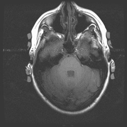
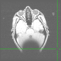
Anatomical image with a line of interference caused by blood flowing through the carotid arteries. Note that a true RF (Radio Frequency) artifact (the image below is not one), would show noise distributed from one side of the image to the other (this one does that) and would occur in every plane of section (this one does NOT do that...to see a montage of all slices in tif format and confirm this claim, click here):
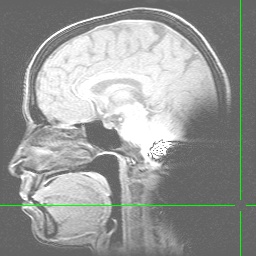
Anatomical images (Axial and Sagittal) showing the effect of a hairband with a little bit of metal on it. Note the signal dropoff at the back of the head resulting from magnetic field inhomogeneities:
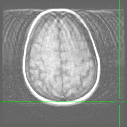
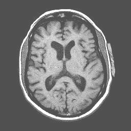
Anatomical image (Axial) with excessive movement (note the ringing effects). Because most people try to hold still, you could expect this effect to be less pronounced in your own images:
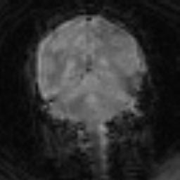
Artifacts (8/8/2003) resulting from some kind of glitch in the receivers for MR1, maybe related to transient noise suppression but Art and Case are unsure of where the problem resides. They will be testing alternatives to see if the can reliably produce it:
Artifacts on the 1.5T scanner with goggles (8/14/2003) The following artifacts were encountered by Scott Hayes in his last 3 scans (each of a different subject) over the course of several days (I am posting only 2 examples). The signal dropoff in the left anterior frontal lobe of spirals has been replicated on the left side of a phantom wearing the goggles. We are not certain that the goggles are the culprit (but they desperately need service anyhow). Anyone who has seen this artifact without the goggles should let us know.
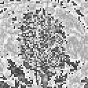
A Possible Minor RF Artifact A minor (possible) artifact appears only in images from subjects wearing the goggles. This possible artifact looks like a small zipper in the middle of the anatomical images. It does NOT extend from one side of the image to the other, but it DOES appear in all slices. The artifact does not create extra outliers (Jen Johnson, afni analysis of the problem), but it is something we might try to correct (which would mean we'd have to figure out why it is happening). Jen Johnson has provided the following image:
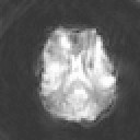
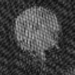
April 26, 2005 Artifacts Note the fluctuating character of the radio frequency noise (background speckles). These are seen in a problem dataset as one scrolls through the timepoints with afni or spm_movie. You must make sure the contrast is high enough to reveal the background noise (this is especially true for spm_movie). Then bad timepoints should flash at you as you scroll past them.
We created image sets in both the 3T and the 1.5T for comparison purposes. Images in the 1.5T scanner were collected with our regular spiral sequence. Images from the 3T were collected with the spiral-in-out sequence. Images were preprocessed and analyzed in afni using the same choices and the same P-value. These images are as follows (Thanks due to Ted Trouard who donated his brain for our purposes): Complex finger tapping on the left and then the right side. The images were analyzed to contrast left and right, with the left being positive. Images show activation on the appropriate side in the motor and sensory strips.
|


