| This
page would not have been possible without the extensive notes and
explanations provided by Jennifer Johnson. Download this page as a
Word
doc if you prefer.
Index
Setup
The
procedures described in this document use both Afni and MGH. MGH
programs depend heavily on Matlab 5.2 or higher. Afni and MGH are
designed for unix systems. Postscript files describing each MGH
function are available by clicking on the links provided below (You
will need a postscript viewer). A postscript viewer is typically
installed by default on unix machines. You should have ghostview,
or similar product, if you are working on a PC.
Tutorial
Dataset
This
is a simple dataset with two runs from a young subject doing an event
related word-stem completion task. The word stems had either few
possible completions or many possible completions and were intermixed
with a control condition. When subjects thought of a completion, they
pressed a mouse button, providing us with a reaction time which was
automatically recorded by DMDX.
We
make the dataset available in raw format: Run1:P09216.gz,
Run2:
P10240.gz, and T1
Anatomy: Anatomicals.tar.gz. The preprocessed data is also available,
if you would like to skip directly to the analysis stage: FuncPreprocessed,
AnatPreprocessed,
Params
(two "par" --parameter-- files that give the timing or
responses for each run, two tpx files which detail timepoints to
exclude from the analysis, and several scripts needed for the analysis).
Finally, we make a finished dataset available (FinishedSelxavg.tar.gz,
FinishedStats.tar.gz,
FinishedBrik.tar.gz).
We will use the same raw data for tutorials in event related analysis
for several programs/processing streams (e.g., we hope, spm99, spm2,
and a pure afni stream).
Scan
Sheet Details:
17 axial slices (nas), thickness (z) 6 mm, skip 0, TR=2000 ms, reps
(ntr)=456. 64x64. FOV 220. Run1= P09216, Run 2= P10240.
T1 anatomicals, same orientation as functionals, 17 slices, 256x256.
3D: 124 slices 256x256.
Slice Alignment: fMRI center: L 6.0, P 3.3, S 28.6, Tilt 125 (AC-PC
105+20).
3D center: L 6.6, P 4.9, I 14.4, 20% off AC-PC.
Overview
Data
is preprocessed in Afni, after which you will have realigned, normalized
(intensity normalized, NOT spatially normalized) bshort files (stop
before building the final normalized BRIKs). Analysis
involves Hemodynamic Response (HDR) averaging, and statistics, after
which the data can be viewed and then exported to Afni for clustering
and dumping. You'll spend a lot of time with Excel.
Optimal
Presentation Order
The
tool optseq,
available on merlin, uses a csh script and matlab
routines to generate optimal sequences for the presentation of event
related data. It has extensive options, but just by using the required
options you can generate text files of potential use (For detailed
advice on using optseq, consult Siobhan Hoscheidt's excellent optseq.doc):
>optseq
-ntp 456 -npercond 75 75 -tpercond 4 4 -o best1
- -ntp
456 is the number of timepoints (reps or ntr)
- -npercond
75 75 tells optseq that there are two noncontrol conditions
and each had 75 presentations (for the tutorial data, conditions
were "few" and "many". There were 75 presentations
of each. The program allows the number of presentations to be
different from each other and assumes that the first number corresponds
to condition 1, the second to condition 2, etc.
- -tpercond
the duration of each presentation in seconds. The program allows
them to be different than each other. We used the timeout values
of 4 seconds here.
- -o
this is the output flag. It should be followed by the filename.
The output is txt file in a paradigm file like format. Column
1 indicates the time at which the stimulus is to be presented,
where 0 is the onset of presentation. Column 2 is the identification
number of each stimulus (0 for control and then 1 to whatever).
The third column is redundant with the first, and indicates the
duration of presentation of each stimulus.
Print
and read the 4 page postscript file: optseq
for more options. The -label flag can be added so that the output
has labels (column 4) as well as condition numbers:
>optseq
-ntp 456 -npercond 75 75 -tpercond 4 4 -label few many -o best1
To
generate multiple output files use -nsessions and -nruns,
where runs are subordinate to sessions.
Understanding
Sessions and Runs:
One
Session, 2 Runs: If you use one session with two runs, optseq will
not necessarily distribute the events evenly in both runs. For example,
if you have one event type repeated 20 times, you may get 12 in
one run and 8 in the other. If you want to split the presentation
into parts, then use multiple runs in one sessions.
2
Sessions, One Run Each: If you use two sessions with one run each
you are guaranteed to get all your reps (20 reps in our example)
in each run. So if you want two different sequences, but you want
each sequence to have the full number of conditions (e.g., 20),
use two sessions with one run each. This is what most people prefer.
(Thanks to Doug Greve for the explanation)
Details
about Timing and Null Conditions
If
npercond * tpercond > npt* TR (default TR is 2
sec), you will receive an error message, referring to line 39 of
fmri_synthpar3.m. Make sure you specify an appropriate npt and TR.
If
npercond * tpercond = npt* TR, optseq will
not generate null (control) conditions as you have not alloted any
extra time for them.
If
npercond * tpercond < npt* TR, optseq will
generate null (control) conditions to fill the extra time.
Specification
of tprescan results in the presentation of trials during the prescan
period. This may not be adviseable since one would presumably be
"throwing out" those scans anyway.
Preprocessing
Functionals
You
should reference the Afni Preprocessing
Tutorial page for details of the afni preprocessing stream.
Below, I try to point out how the preprocessing of this data differs
from the block tutorial data. grecons5x and rename_spiral are the
same (though, obviously, the names of the Pfiles are different).
Data
collected after September 2002? See
Scanner Updates for information about
new grecon protocols as of September, 2002.
I
give examples below for Run1 and assume you can alter the parameters
(file names and directory names) for Run2. The to3d command requires
a different TR (456) for these event related runs than for the original
block tutorial.
The
to3d command for Run1 should look like this (depending on your directory
name and what you want to name the output file):
>to3d
-epan -prefix run1 -time:tz 456 17 2000 seqplus 'Run1/P09216.*'
Outlier
Troubles?
If your data has outliers in it, to3d will refuse to reconstruct
it. Should you wish to proceed in an unprincipled way and reconstruct
the data despite the outliers, learn more about to3d
from its glossary entry.
In
the graphical usr interface panel (gui), the x, y, and z orientations
are the same as in the block tutorial set: Right Anterior Superior,
FOV is 220, and z (thickness) is 6.
>3dvolreg
-verbose -Fourier -prefix run1_3dreg -base 3 -dfile run1_3dreg.log
run1+orig
>from3d
-input run1_3dreg+orig -prefix run1_3dreg
>afnireg2bshort
-i run1_3dreg -fgs 1 -nas 17 -nfs 456
>inorm
-i run1_3dreg -o run1_norm
(Here
I have deviated slightly from the naming strategy employed in the
Afni preprocessing tutorial. I've made the name of the output a
bit shorter)
Anatomicals
T1
anatomy files should be renamed and converted
to bshorts w MR2bshort.
Things
not as simple as you were hoping?
There are some notes and tricks you should check on, here.
If your data was collected after September 2002, then check Scanner
Updates for more information about how this effects rename_anat
and to3d for your anatomicals.
From
the directory containg your anatomicals run rename_anat:
>rename_anat
(Enter
the prefix of your E files when requested: E18767S3)
From
that same directory, run MR2bshort:
>MR2bshort
-i E18767 -s 3 -fs 1 -ns 17 -o brain -slice3w
If you type MR2bshort with no arguments, you'll get a usage
message. Above, we tell MR2bshort the input prefix -i E18767,
the series number -s 3, the first slice -fs 1,
the number of slices -ns 17, the output prefix -o brain,
and that we would like the filename to devote 3 characters to
numbering (this will put leading zeroes before 1 and 2 digit slice
numbers) -slice3w.
Processing
Data collected after September 2002? See
information on the Scanner Updates page
about MR2bshort2.
Parameter
files
Purpose:
The paradigm file is analogous to the waver 1D file for afni and
the model specification in SPM. It describes the timing of control
and stimulus conditions throughout the functional run. For an event
related paradigm, each subject run should be associated with a unique
parameter file (because each run will be associated with a unique
set of reaction times).
The
paradigm file is a text file containing two columns of numbers.
The first column contains the stimulus onset time (Clock on Time
or COT in DMDX), in seconds, relative to the time at which the first
stored image of the run was collected. The second column represents
the condition code for each stimulus. By convention, the code 0
represents the control, baseline or fixation condition. The other
conditions are to be numbered sequentially starting with 1.
For
the event related paradigms, the time (column one) should be the
time of stimulus onset and need not be an integer multiple of the
TR. For example, in the paradigm file below, the first stimulus
(condition 1) was presented 2 seconds before the first image was
acquired, the second stimulus (condition 3) at the first image,
and the third stimulus (fixation) at 4.5 seconds into the imaging
run.
-2.0 1
0.0 3
4.5 0
DMDX
produces timing information for us. The DMDX output ("Item
Number", "Reaction Time" and "Clock on Time")
can be converted into a parameter file and a tpx file.
You
may wish to examine the
original DMDX file for Run1 along with the corresponding par
file and tpx
files.
The
parameter file includes the COT values (divided by 1000; because
DMDX provides values in ms, but the par file needs to include them
in seconds). Next, the par file includes the condition. The condition
values are the factors that you can play with most. They may be
based simply on the type of trial presented at that point in time,
or, be a complex combination of information about trial type and
reaction times. In this particular case, the experimenter used a
variety of differently derived par and tpx files for the experiment.
The examples provided with the tutorial were derived as follows:
Trials were either words with few completions, many
completions or controls. Reaction times were divided into
three groups: shorter than the median time, longer
than the median time, or time out (no answer). Trials in
the few and many conditions were then ranked and paired in terms
of reaction time and paired off so that each "few" condition
had a paired "many" condition with a similar RT. Timeout
RTs (-3950) and unpaired trials were treated as condition 5 and
included in the tpx file as time points to be excluded. Control=0,
Few_Short=1, Many_Short=2, Few_Long=3, Many_Long=4.
When
you are finished creating the parameter and tpx files, save them
as text files. If possible, save them as unix text files (this gets
rid of the ^M or <cr> characters at the ends of the lines).
Make sure there are no extra lines at the ends of the files. For
the tutorial, you don't need to create these files. You can download
them (Params).
Analysis
Begin
by putting the preprocessed data into a directory. I suggest the
following: a directory containing the script, par and tpx files
(the contents of Params.tar.gz),
and 3 subdirectories: Run1 (containing the normalized run1_norm
bshort and hdr files), Run2 (containing the normalized run2_norm
bshort and hdr files), and Anatomy (containing the brain*.bshort
and hdr files). You are not obliged to use particular directory
names or a particular directory structure, but you either need to
use the recommended names/structures or revise the provided scripts
so that they point to the correct directories and files. Create
several other directories, as follows:
>mkdir
Selxavg
>mkdir
Stats
>mkdir
Brik
Preprocessed
data for Run1 and Run2 are here.
The Anatomical files are here
(though you may prefer to use the data you have preprocessed instead).
selxavg
selxavg
is a program for performing selective averaging and deconvolution
of event related fMRI images for a single subject over multiple
runs (it generates average hemodynamic response files). It
can also average data from blocked designs. It will generate two
bfloat and hdr file for each image slice (17 slices in our case).
The first set of images (ours will be called select*) contain the
selective averages and standard deviations. The second set of images
(select-offset*) store the offset or baseline of each voxel. The
program takes ~20 minutes to run on the tutorial data.
- In this example, the first section of the script does all the
work (the second section simply returns an error message if the
program fails in some way).
- The \ (backslash) at the end
of each line in the first section indicates that the command continues on
the next line down. The backslash serves to break up a command
that would normally be one long line.
- Note:
The \ is very tricky to use. You must not have any
characters, including spaces or a carraige return after the
backslash. If you have trouble running a script, try removing
all the backslash characters at the ends of lines...it won't
be as pretty, but it might run better. If
you are really dedicated to finding the problem, try using
octal dump to display all characters:
>od -tx1a selector
will show you all the characters in selector. You want to
see \ nl and not, for example, \ sp nl (nl=new
line, sp = space).
- -o
Selxavg/select the
-o (output) flag precedes the directory you want selxavg
to put output files in, and the name you want to give the outputs
(I call them "select" here, so we can remember which
program generated them, but you can call them anything you want).
- -nslices
17 This
indicates that there are 17 slices
- -TR
2 The
TR is 2 seconds
- -timewindow
20 The
default time length for the hemodynamic response is 20 seconds.
Timewindow size should be in seconds, and be divisible by TR. It
includes the prestim.
- -prestim
4 A
portion of the timewindow (in seconds) that precedes the stimulus
onset. This can be used as a sanity check to make sure the subject
is not anticipating the stimulus. Use -prestim of 2-3 TRs
to create a baseline points for each condition.
- -detrend
remove
silly trends (see below for more technical description)
- -hanrad
1.5 Radius
(in voxels) of a Hanning Spatial
filter. A radius of 1 or less has no effect. The larger the
radius, the more smoothing.
- -nconds
6 We
have 6 conditions. They are: Control=0, Few_Short=1, Many_Short=2,
Few_Long=3, Many_Long=4, TimeOuts and Unpaired Trials=5.
- -i
Run1/run1_norm -p run1_par.txt
-i
Run2/run2_norm -p run2_par.txt multiple -i flags are
used to combine runs. However, a single -i flag and its arguments
could be used if you only wanted to process one run at a time.
- Type selxavg at your shell prompt for the following usage
information:
USAGE:
selxavg [-options] -i instem1 -p parfile 1 [-i instem2 -p parfile2
...] -o outstem
instem1 - prefix of input file for 1st run
parfile1 - path of parfile for 1st run
[-tpexclfile file1] - file with timepoints of 1st run to exclude
[instem2] - prefix of input file for 2nd run
[parfile2]- path of parfile for 2st run
[-tpexclfile file2] - file with timepoints of 2nd run to exclude
outstem - prefix of .bfloat output files
NOTE:
you must specify all runs to process now
Options:
-TR <float> : temporal scanning resolution in seconds
-TER <float> : temporal estimation resolution <TR>
-timewindow <float> : length of hemodynamic response in
seconds <20>
-prestim <float> : part of timewindow before stimulus onset
(sec)
-nobaseline : do not remove baseline offset
-detrend : remove baseline offset and temporal trend
-rescale <float> : rescale target (must run inorm first)
-nskip <int> : skip the first n data points in all runs
-hanrad <float> : radius of Hanning spatial filter (must
be >= 1)
-gammafit delta tau : fit HDR amplitude to a gamma function
-timeoffset <float> : offset added to time in par-file in
seconds <0>
-nullcondid <int> : Number given to the null condition <0>
-firstslice <int> : first slice to process <auto>
-nslices <int> : number of slices to process <auto>
-percent pscstem : compute and save percent signal change in pscstem
-nonwhite <int> : don't assume white noise (spec n autocor)
-ecovmtx stem : compute and save residual error covariance
-basegment : force segmentation brain and air (with nonwhite)
-mail : send mail to user when finished
-eresdir dir : directory in which to save eres vols
-signaldir dir : directory in which to save signal vols
-monly mfile : don't run, just generate a matlab file
-synth seed : synthesize data with white noise (seed = -1 for
auto)
-parname name : use parname in each input directory for paradigm
file
-cfg file : specify a configuration file
-umask umask : set unix file permission mask
-version : print version and exit
stxgrinder
stxgrinder
generates significance maps for fmri experiments that have been
prepared with selxavg.
Example
script for stxgrinder (we'll call it stx): This
script will process 3 different contrasts, one after the other.
The first is to compare two "active" conditions to the
"control" condition. The next two compare those two active
conditions to one another. (Advanced options may be available in
mkcontrast
documentation)
stxgrinder -i ./Selxavg/select -firstslice 0 -nslices 17 \
-a 1 -a 2 -c 0 -testtype t -ircorr -delta 8 -tau 1.25 \
-format log10p -o ./Stats/ta12c0
stxgrinder -i ./Selxavg/select -firstslice 0 -nslices 17 \
-a 1 -c 2 -testtype t -ircorr -delta 8 -tau 1.25 \
-format log10p -o ./Stats/ta1c2
stxgrinder -i ./Selxavg/select -firstslice 0 -nslices 17 \
-a 2 -c 1 -testtype t -ircorr -delta 8 -tau 1.25 \
-format log10p -o ./Stats/ta2c1
In
this example we are running 3 commands, each of which would normally
be on a different command line. You can see that the
backslashes \ used for formatting are not used on every
line, but rather on lines that are within a single command (each
command starts with the program name stxgrinder).
- -i
./Selxavg/select the -i flag (input) is followed by the stem
of the image files to be used by stxgrinder for its calculations
- -firstslice
0 The first slice in the series (slices are numbered 0-16)
- -nslices
17 The number of slices (17)
- -a
1 -a 2 -c 0 a=active, c= control: indicate which conditions
to treat as active (few-short and many-short), and which to treat
as control
- -testtype
t Use a t-test (other tests are possible)
- -ircorr
correlate the hdr to the ideal hdr
- -delta
8 Along with tau, this helps describe the shape of the hdr.
Delta is the time in seconds between stimulus onset and the start
of the time at which bloodflow starts to increase. A typical value
is 2.25.
- -tau
1.25 Together with delta, this describes the shape of the
ideal hdr. Specifically, tau controls how fast the hdr
rises and falls. A typical value is 1.25.
- -format
log10p If you use -format p (which allows you to transfer
p values back to AFNI) , activations peaks are sometimes dropped
when the significance is great (~log 50.+) Using "-format
log10p" solves the problem. You end up with log values in
AFNI, but a fair trade for keeping all peak activation voxels.
FYI: log 4 = p .0001, log 3 = p .001, log 2 = p .01 etc.)
- -o
./Stats/ta12c0 The location for the output files of the process
For
the options listed here, type stxgrinder at your shell prompt:
USAGE:
stxgrinder [-options] -i instem -o outstem
instem - stem of .bfloat selxavg input volume
outstem - stem of .bfloat signficance map volume
Options:
-cmtx cmtxfile : contrast matrix file (see mkcontrast)
-a a1 [-a a2 ...] : active condition(s)
-c c1 [-c c2 ...] : control condition(s)
-allvnull : all vs condition 0 (instead of -a and -c)
-delrange dmin dmax : delay range to test <prestim,timewindow>
(sec)
-ircorr : correlate with ideal HDR
-delta : delta of ideal HDR
-tau : tau of ideal HDR
-testtype : stat test type (t,<tm>,Fd,Fc,Fcd)
-pmin stem : stem for min p value from tm test over delrange
-ipmin stem : stem for index of min p value (with -pmin)
-statstem stem : store statistic in volume stem
-format string : lnp, <log10p>, p
-monly mfile : do not run, just create matlab file
-firstslice <int> : first slice to process <auto>
-nslices <int> : number of slices to process <auto>
-version : print version and exit
yakview
Use yakview to view the results of your earlier analyses. Yakview
can display the image:
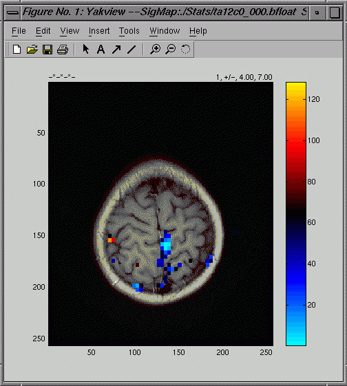
and
a graph of the hemodynamic response (HDR) at a chosen voxel:
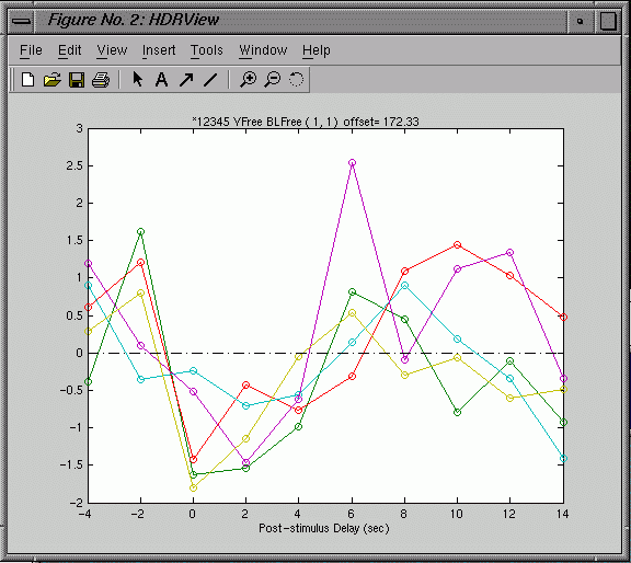
- Click
on a voxel in the image & hit g to display the graph
of the corresponding HDR for that voxel.
- Hit
h in the figure window to bring up help for the figure
window (there is a different help for the brain image and the
graph window).
- The
null condition is set to zero (0). Active conditons are displayed
in different colors. In the graph window press "1" (for
condition 1) or "2" (for condition 2), etc. to toggle
the graph lines on & off and see which line goes with which
condition.
- For
printing, change the thickness of the lines using the options
in pull down matlab menus in the graph window. Use file-export
to save image/graph as *.bmp. You can also save the images as
.fig files--matlab figure files--and edit them later to alter
axes, axis labels, titles, colorbar etc.)
A
script called superyak is installed on our sgis. Type superyak for
help. The superyak script will allow you to view multiple slices
by entering a single command like this:
>superyak
./Anatomy/brain ./Stats/ta12c0 ./Selxavg/select 4 7 0 3
This
is a very simple script, so it has no flags, and you must include
all arguments and put the arguments in the correct order: The path
to the anatomy files, the path to the stats files, the path to the
selxavg files, the thmin value, the thmax value, the first slice
to view, the last slice to view.
This
script will bring up one image at a time. You have to close the
image window after viewing each slice to move from one image to
the next. Here is an example of the yakview command:
yakview
-i ./Anatomy/brain -sn 0 -p ./Stats/ta12c0 -thmin 4 -thmax 7 -h
./Selxavg/select
- -i
./Anatomy/brain The input flag is followed by the directory
and prefix of the anatomical file to use for overlay.
- -sn
0 is the slice number to view.
- -p
./Stats/ta12c0 The -p flag is followed by the stem of the
stats map you want to overlay on the anatomical.
- -thmin
4 This is the minimum intensity allowed for the stats overlay
voxels to be displayed as color.
- -thmax
7 The maximum intensity of the stats overlay that is associated
with a unique color. Values greater than this will be displayed
as the same color as the max.
- -h
./Selxavg/select The directory and stem for the average hemodynamic
response files
Type
yakview at the shell prompt to see the following usage information:
USAGE:
-i imgstem -sn slicenum -p sigstem -th threshold -f pformat -h
hdrstem
-i imgstem: stem of image to view
-sn slice number
Options:
-p sigstem: stem of stat map to overlay
-thmin threshold: min threshold for stat overlay (4)
-thmax threshold: max threshold for stat overlay (7)
-h hdrstem: stem of hemodynamic averages
-r rawstem: stem of raw data to plot
-nskip n : skip when displaying raw timecourses
-off offsetstem: stem of offset volume
mkmosaic
You
could use mkmosaic to make a mosaic of all images at once. Tip:
This process takes a bit of time to create & to load, but then
you can easily move from one image to the next, and use zoom to
see a particular slice up close. You
need to first make a mosaic of each image type and then use yakview
to display overlays:
>mkmosaic
Anatomy/brain
>mkmosaic
Selxavg/select
>mkmosaic
Stats/ta12c0
>yakview
-i ./Anatomy/brain_mos \
-p ./stats/mfvm/ta12c0_mos -thmin 4 -thmax 7 \
-h ./selxavg/select_mos
Make
BRIKs for AFNI Clustering & Output
NOTE:
You'll need all the BRIKs in same directory for AFNI to work. Cd
to the brik directory and run 'to3d' from there, so it will write
all the briks to the same place. (also convenient when you want
to dump/sort files after the nth time you change your mind about
which stats you wanted to use in stxgrinder.)
You'll
want to convert the bfloat "stats" files AND the bfloat
functional files into BRIKs. Also convert the anatomical bshorts
to briks. Because you'll want all of them to end up in one directory,
go to the the Brik directory you created in the Setup step above
and run to3d from there:
>cd
Brik
Because
all subsequent steps are in Afni, you will be working exclusively
in the Brik directory.
Transfer
functional data to AFNI format from brik dir:
>to3d -epan -prefix select -time:tz 120 17 2000 seqplus 3Df:0:0:64:64:120:'../Selxavg/select_0??.bfloat'
- number
of time points= 120; timewindow (from the selxavg command)/TR
(secs)*(2*number of conditions)=(20/2)*2*6
- If
you get this calculation wrong, Afni won't build the brik.
If it builds the brik, you did it right.
- Orientation=
Right, Anterior, Superior. FOV=220, z=6
- By
using 0?? instead of ??? in the filename, we help
the program avoid trying to add in the wrong files (e.g. select_mos.bshort).
- This
file looks empty...do not despair, this is normal.
Transfer
stats output back to AFNI for clustering and further analysis:
>to3d
-prefix stats -fim '3Df:0:0:64:64:1:../Stats/ta12c0_0??.bfloat'
Orientation=
Right, Anterior, Superior. FOV=220, z=6
In the above command, we use 1 for the number of timepoints.
This is because the file is an average of all timepoints for each
slice, and thus it is a simple 3d file. The f in 3Df means
that we are using floats as input.
This
file looks like a big square of intensity values...Maybe you can
make out brain edges if you squint, but don't count on it.
Make
anatomical BRIK from the brain bshort files:
>to3d -anat -prefix brain ../Anatomy/brain_0??.bshort
Masking
off the Brain
This
step will allow you to do two things of interest:
1) Check that your runs are aligned to one another
2) Remove all activation that falls outside the functional brain
image prior to clustering and analysis. This is useful when you
get to the stage of looking at Excel files, because it helps you
to cull the data so you are just looking at what is most meaningful.
Some users may want to review the masks
page in order to create a mask for a single brain area. This could
be used to limit surviving activation data to a single region, (e.g.,
the parahippocampal gyrus).
From
your Brik directory:
>to3d
-epan -prefix run1 -time:tz 456 17 2000 seqplus 3D:0:0:64:64:456:../Run1/run1_norm\*.bshort
In
the to3d window: RAS, FOV=220, voxels are square, z=6.
Repeat for run2
>3dAutomask run1+orig
The
3dAutomask command takes a while
to run and, by default, produces a file called automask+orig. There
is no need to repeat it for run2.
1) Check that your runs are aligned to one another
>afni
In the afni window, click axial image to display an image. The automask+orig
is a single colored functional image in the shape and location of
your epan image (see the 3dAutomask link). You will need to click
"See Function" and make sure automask is selected under
"Switch Function". You may want to view this mask overlaid
on brain (This will show you where there is signal dropoff). View
automask overlain on run1 to see how well the mask matches the image.
If you hate the match, you can run automask with various options
to alter it. Try
>3dAutomask -help
to see your options.
You can overlay the automask on run2 to make sure it is acceptably
aligned with run1
2)
Use mask multiplication (3dcalc) to remove data you don't care about
(e.g., activation outside the brain):
>3dcalc
-prefix stat_masked -a automask+orig -b stats+orig -expr 'a*b'
Now
you have an output file stat_masked that you can use in subsequent
steps.
Make
AFNI Images Display like yakview
You
should take a look at your briks to assure yourself that they look
okay.
>cd
Brik (if you aren't already there)
>afni
(You will also need to afni window for clipping and clustering,
below)
- Axial
image: Switch Anatomy-> brain
- Click
See Function
- Click
Define Function
- make
colorbar 2 divisions: top = none, bottom =red
- click
"positive only" box
- Select
stats (fim) brik for overlay
- Click
Switch Function to view other functional datasets
Clip
Stats fim Brik
Edit
your statistical data to remove all values in a given range.
- Define
Datamode=>plugins=>3Dedit
- Pass
1
- Dataset
Input: stat_masked+orig [fim]
- clip
lower = -1, upper = 0 Unscaled? FALSE (This
clips negative p values)
- Prefix
(OUTPUT): clip1
- Run
and Keep
- Pass
2
- INPUT
clip1
- clip:
lower = .0011 upper = 1 Unscaled? FALSE (This
clips p values not significant at .01 or better)
- Prefix
(OUTPUT): clip2
- Run
and Close
Cluster
Data
- Define
Datamode=>plugins=>3D
Cluster
- Dataset:
input clip 2 created from 3dEdit step above.
- Params:
TYPE = keep
- RADIUS
= 6.1 (goes beyond the 6mm voxel "thickness")
- MinVol(ul)
= 180 (each voxel is ~70 ul (3.4*3.4*6), so to get it to make
clusters with at least 2 voxels touching, use any number 142-209.)
- Do
not select erode/dilate or threshold
- Prefix
(OUTPUT): cluster
- Run
and Close
3dmerge
Two
step process:
>3dmerge
-prefix merge_clust -2clip -100 4 -1clust 6.1 180 -1erode 50 -1dilate
cluster+orig
The
first command clips negative and insignificant intensity values
and then erodes away narrow bridges between clusters.
- -prefix
merge_clust the name for the output
- -2clip
-100 4 clip intensities in the range -100 to 0 (the negative
intensities) and values not significant at p = log 4 (.0001),
(-100 is a good choice just because it is so huge, you'll get
everything)
- -1clust
6.1 180 this clusters significant voxels, radius = 6.1mm,
min volume = 180ul,
- -1erode
50 -1dilate then uses the erode &
dilate features. Erode unless 50%
of the voxels within the radius (6.1) are nonzero. Dilate
to restore the size of any eroded voxels if there remains a non-zero
voxel within the radius (6.1). Erode & dilate because it severed
narrow "bridges" between 2 active clusters (in some
cases at least), while preserving the original cluster size. Using
erode alone caused some small clusters to disappear.
- cluster+orig
is the name of the input file.
>3dmerge
-prefix merge_clustnum -1clust_order 6.1 71 merge_clust+orig
The
second command assigns a number to each cluster, ordered by size.
This is useful for sorting voxels/clusters in Excel.
- -1clust_order
6.1 71 All
voxel intensities within a cluster (clusters defined by the radius
and ul) are replaced by the cluster size index (largest cluster=1,
next largest=2 etc.)
- The
input to the second 3dmerge command merge_clust+orig
is the output from the previous command
3ddump98
This
plugin just outputs AFNI data to a text file, which can later be
transferred to Excel. The mask file has 5 columns: AFNI ID, X, Y,
Z coordinates, and cluster number.
>afni
- Define
Datamode=>Plugins=>3Ddump98
- Dataset
= merge_clustnum (output file from last 3dmerge)
- Intensity
mask: Min = 1 Max = 100 (all the cluster #s) (1-100
is a big enough range to get everything)
- Output
= Imask (for Intensity Mask)
- Do
not select subbrik info or thresh mask
- Click
on Run & Keep, so it will tell you the number of voxels output
( Should
be a small number)
- Viewing
cluster # on images: If
you open all 3 image window types (sagittal, axial, coronal) the
cluster number will be displayed for the voxel you click on in
the lower right corner of the AFNI window (next to the color scale).
- Quit
- Your
output files will be two text files: Imask contains 5 columns
of data (Afni ID number, x,y, and z coordinates, cluster
number). It will contain one row for each voxel output
(e.g., 629). Imask.log tells you what parameters you used,
the number of voxels output (hence, the number of rows in Imask),
etc.
4ddump
This
plugin extracts voxel timecourses for each xyz coordinate in the
Imask file.
What
you'll get is a big spreadsheet of all of the active voxels in all
of your clusters. The first column is an AFNI ID number. The next
3 columns are the x, y, & z coordinates, respectively. The rest
of the columns are the voxel data by time and condition. For example,
the tutorial data has 6 conditions, and 10 timepoints (10
timepoints because the timewindow is 20 seconds and the TR is 2,
hence 20/2 timepoints). The first 10 columns are the intensity
value at each timepoint for condition 0. The next 10 columns are
the standard deviations, for condition 0. It repeats this way for
the rest of the conditions.
>afni
- Define
Datamode=>Plugins=>4DDump
- Data
= select+orig
- Ignore
= 0
- Detrend
= n
- Mask
file = enter the output file from 3DDump98, for FVMFMRI: Imask
- Ncols
= 5 (can check # of columns by viewing mask file in unix)
- Select
xyz mask
- Select
output = 4ddump_data
- The
command produces 4ddump_data and 4ddump_data.log
Merging
Files and Excel
Although
you can merge and label the files in Excel, we also have a script
(/usr/local/bin/MGHlabel) that can automatically merge and label
files:
>MGHlabel
-i1 Imask -i2 4ddump_data -o OutE18767 -tp 10 cx fs ms fl ml to
In
this command we name the two input files to be pasted together,
first -i1 (the mask file), then -i2 (the 4ddump file).
We provide a name for the final output file -o OutE18767,
we identify the number of timepoints (timewindow/tr) -tp 10,
and then we list our condition labels: cx fs ms fl ml to.
scp
your output file (or the Imask and 4ddump_data files) to a PC for
analysis. In excel, import the file as delimited
with both tabs and spaces used as delimiters. Check the file and
remove redundant information once you are comfortable. Typically,
you will then want to label your columns and identify the anatomical
region of each voxel, then sort by anatomical region and get means
for each anatomical region.
|